Modbus TCP Direct
1. Functional Overview
ThingsPanel's Modbus TCP access service supports direct connection to industrial devices, automatically collecting data and reporting to the platform. Key features:
- Visual Configuration: Web interface to configure device parameters and data address tables.
- Smart Polling: Flexible data collection strategies and cycle configuration.
- Device Control: Supports writing to coils and registers for control.
- Connection Management: Automatic reconnection, connection pool management, status monitoring.
2. Quick Start
Prerequisite: Modbus TCP connectivity service is deployed and registered to the platform.
2.1 Prepare Device Information
Collect the following device information before configuration:
| Parameter | Description | Example |
|---|---|---|
| IP Address | Device IP Address | 192.168.1.100 |
| Port | Modbus TCP Port | 502 |
| Slave ID | Device SlaveID | 1 |
| Data Address | Register Address Range | 40001-40010 |
2.2 Create Device Template
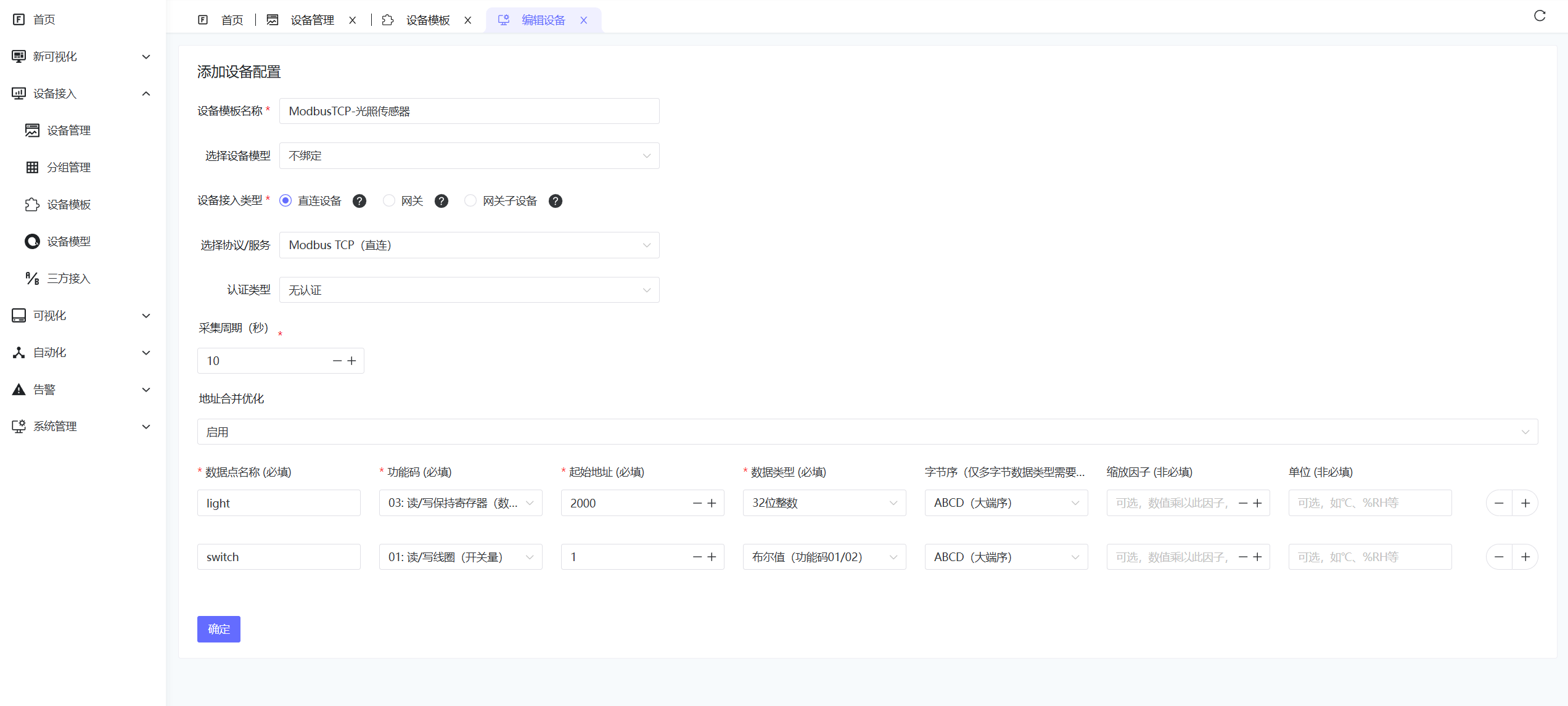
- Go to Device Connectivity - Device Templates.
- Select Access Type: Direct Device.
- Select Modbus TCP (Direct), set Authentication Type to None.
- Fill in Collection Interval, enable Address Merge Optimization if needed.
- Configure Collection Parameters as follows:
| Config Data | Description | Example |
|---|---|---|
| Data Point Name | Unique Identifier | temperature |
| Function Code | Modbus Function Code | 03 (Read Holding Registers) |
| Start Address | Register Address | 40001 |
| Data Type | Data Parsing Type | Float32 |
| Endianness | Big/Little Endian | Big Endian |
| Scaling Factor | Optional, Value Scaling | 0.1 |
| Unit | Optional | °C |
2.3 Create Device
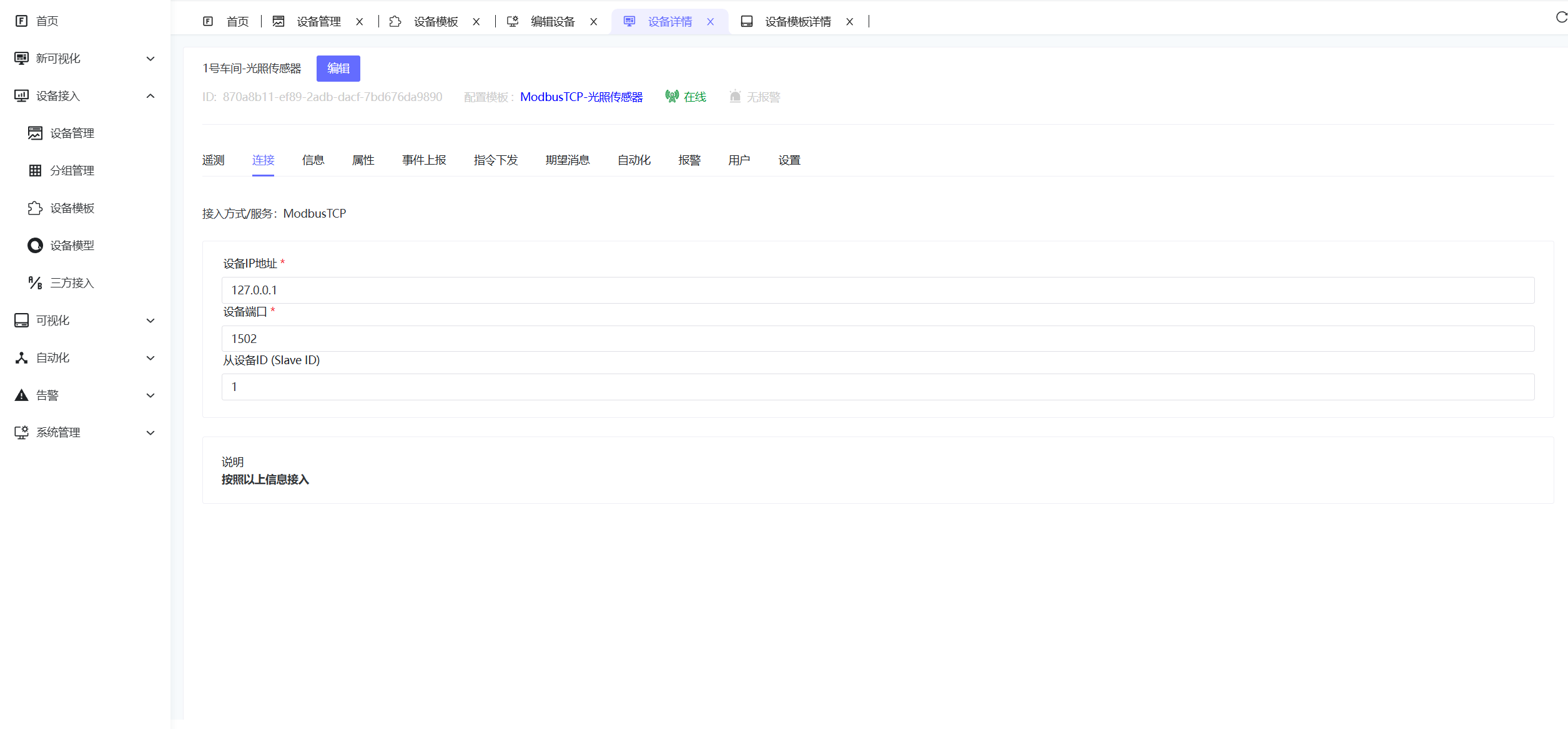
- Go to Device Connectivity - Device Management → Add Device.
- Fill in device name, select device type: The device template created in the previous step.
- Enter Device Details, select the Connection tab, fill in Device IP, Port, Slave ID, and Save.
Device IP: 192.168.1.100
Port: 502
Slave ID: 1
3. Data Address Table Configuration
3.1 Add Data Points
Click Data Address Table → Add Data Point to configure parameters:
| Config Item | Description | Example |
|---|---|---|
| Data Point Name | Unique Identifier | temperature |
| Function Code | Modbus Function Code | 03 (Read Holding Register) |
| Start Address | Register Address | 40001 |
| Data Length | Register Quantity | 2 |
| Data Type | Data Parsing Type | Float32 |
| Endianness | Big/Little Endian | Big Endian |
| Scaling Factor | Value Scaling | 0.1 |
3.2 Supported Function Codes
| Function Code | Description | Address Range |
|---|---|---|
| 01/05 | Read/Write Coil Status | 00001-09999 |
| 02 | Read Discrete Input | 10001-19999 |
| 03/06 | Read/Write Holding Register | 40001-49999 |
| 04 | Read Input Register | 30001-39999 |
3.3 Data Types
| Type | Registers Occupied | Description |
|---|---|---|
| Bool | 1 | Boolean |
| Int16 | 1 | 16-bit Signed Integer |
| UInt16 | 1 | 16-bit Unsigned Integer |
| Int32 | 2 | 32-bit Signed Integer |
| UInt32 | 2 | 32-bit Unsigned Integer |
| Float32 | 2 | 32-bit Float |
| Float64 | 4 | 64-bit Float |
4. Device Control
4.1 Supported Control Types
- Coil Control: Function Code 05 (Single Coil)
- Register Control: Function Code 06 (Single Register), 16 (Multiple Registers)
4.2 Control Operations
Real-time control can be performed from the platform by sending control commands using the configured data point names:
{
  "temperature": 15.2,
  "switch": 1,
  "speed": 1200
}
Explanation:
temperature: Set target temperature valueswitch: Control switch state (0=OFF, 1=ON)
5. Troubleshooting
5.1 Common Issues
| Issue | Possible Cause | Solution |
|---|---|---|
| Device Disconnected | Network unreachable, IP error | Check network, confirm device IP |
| Read Fail | Address error, unsupported function code | Check register address and function code |
| Data Abnormal | Data type error, endianness error | Confirm data type and endianness |
| Control Fail | Device read-only, permission denied | Check write permission and function code support |
5.2 Debugging Suggestions
- Step-by-step: Configure a few data points first, then add more.
- Tools: Use Modbus tools to verify communication.
- Logs: Check system logs for detailed errors.
- Network: Use ping to test connectivity.
6. Performance Optimization
6.1 Address Merge Optimization
Enable address merge optimization to improve efficiency:
- Continuous Addresses: System automatically merges continuous register addresses.
- Reduce Requests: Reduces Modbus request count, improving response speed.
- Suggestion: Configure related data points in continuous address ranges.
6.2 Collection Cycle Setting
Set appropriate collection cycles:
- High Frequency: Important parameters (1-5s).
- Normal: General parameters (10-30s).
- Status: Slowly changing parameters (60s+).